


Part Data
- 0
- 28
- 2637
Downloads Available
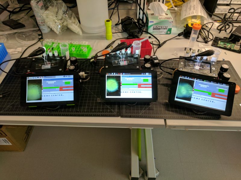
What does this device do?
miniDrops is a 3D printed, low-cost, small-footprint microfluidic controller most suitable for droplet microfluidics [Drop-seq]
This project is open-source. I am currently not engaged in any further development of the system.
I will attempt to maintain the bill of materials with regards to correct part numbers and current costs to the best of my ability. However this is not always possible as companies/distributors change part numbers and costs or discontinue parts. Please send a DM to me if you suspect any inconsistencies in the bill of materials or have any questions regarding any of the components, their purpose, or if a part can be used as a suitable replacement.
DISCLAIMER
Copyright (c) 2018 William T. Stephenson, New York Genome Center
Permission is hereby granted, free of charge, to any person obtaining a copy of this hardware, software, and associated documentation files (the "Product"), to deal in the Product without restriction, including without limitation the rights to use, copy, modify, merge, publish, distribute, sublicense, and/or sell copies of the Product, and to permit persons to whom the Product is furnished to do so, subject to the following conditions:
The above copyright notice and this permission notice shall be included in all copies or substantial portions of the Product.
THE PRODUCT IS PROVIDED "AS IS", WITHOUT WARRANTY OF ANY KIND, EXPRESS OR IMPLIED, INCLUDING BUT NOT LIMITED TO THE WARRANTIES OF MERCHANTABILITY, FITNESS FOR A PARTICULAR PURPOSE AND NONINFRINGEMENT. IN NO EVENT SHALL THE AUTHORS OR COPYRIGHT HOLDERS BE LIABLE FOR ANY CLAIM, DAMAGES OR OTHER LIABILITY, WHETHER IN AN ACTION OF CONTRACT, TORT OR OTHERWISE, ARISING FROM, OUT OF OR IN CONNECTION WITH THE PRODUCT OR THE USE OR OTHER DEALINGS IN THE PRODUCT.
Keywords:
Material:
Fabrication Technology:
Publications: |
|---|
License:
Attribution: CC BYLeave a Reply Cancel reply
You must be logged in to post a comment.
8/15/17 – Updated the build manual (v12) to have higher RES images, user manual is also found in the design files -Will
This is a really interesting field. Does micro fluidics support Computers
Not really sure what you are asking here. Microfluidics deals with the precise manipulation of fluids at the micron scale. These systems can interface with computers to perform fluid control operations, a prime example being this project and other projects on the Metafluidics repository.
8/24/17 – I will be updating the electronics to allow for faster flow rates and thus reduced [Drop-seq] run time. The BOM and new instructions on electronics modification will be updated in the Build Manual. Look for these updates in the coming week. -Will
8/29/17 – I have updated the BOM and Build manual. Two electronic components were replaced (IC3 and R5 on PCB). See the BOM for details.
-Will
You should consider submitting a manuscript focused on the hardware construction and characterization to HardwareX, it would be a great fit.
https://www.journals.elsevier.com/hardwarex/
cheers,
Todd
How large are the droplets (diameter) created from the chip?
Thanks,
Cyrus
Hi Cyrus,
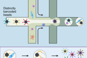
The droplet size is dictated by the microfluidic chip used and the pressures. Both are adjustable! Typically using the modified “Drop-seq” chip I can get droplet sizes up to about 130um (diameter). Personally I haven’t had a reason to go much larger than that.
-Will
Thanks so much!
I was thinking about modifying the miniDrops system to encapsulate hemoglobin in a membrane and I was wondering about the best way to contact you to ask more questions about it.
Thanks again,
Cyrus
10/10/17 – Updated the bill of materials (BOM). There was an error on one of the parts: Honeywell TruStability pressure sensor. The correct part number is SSCDLNN015PGAA5-ND and can be found at the following link:
https://www.digikey.com/products/en?keywords=SSCDLNN015PGAA5-ND
-Will
Hi Will,
I got the HSC. There is only a difference in the operating temperature range.Should work with both?
Cheers,
Hans
Amazing! Thank you for sharing this!
No problem! Thanks for building the repository!
11/16/17 – Updated the bill of materials (BOM) to v4. Corrected the part number for the Airtrol regulators (part 7) and removed ambiguous pre-part number for mx7 solenoid valve. Parker Hannifin precision fluidics may have altered the solenoid valve part number and I will check back for the correct configuration (product number)
Just a suggestion to those interested in building the instrument: The PCB required for this instrument is a 4-layer board and can be pricey if bought at quantity 1. The more PCBs ordered, the lower the individual board cost. I would suggest connecting on this forum to make a group order of the circuit boards to save money. Also feel free to shop around at different PCB manufacturers for the best price.
-Will
2/27/18 – Updated the User_manual to v2. Changed PE2 to PE3 in the ‘you will also need’ section. PE3 is the correct tubing to be used with this instrument for the given New England Small Tube stainless steel tubing, NOT PE2.
Hi, I can’t seem to find the diagram for the PCB board. Where is this file located and how do I order one of these?
Hi Benjamin,
The PCB is contained in the “mDSv15-Gerber-files-4-layer-sfe-CAM” files, you could order the PCB from almost any PCB manufacturer that has the ability to make 4-layer boards such as OSH Park, Royal Circuit Solutions, Ecpress PCB, etc. It may be more cost effective to reach out to others interested in purchasing PCBs as they typically take orders for 3 or more boards.
-Will
Hi Will,
I’m making good progress building the device. Is there a vendor that already has the mDS microfluidic chip of your design ready made? Alternatively, have you tested the designs from the McCarroll lab (e.g. ready made chips from Nanoshift)?
Thanks!
Scott
Hi Scott,
If you intend to perform Drop-seq, the chips from McCarroll lab will not work with this system. The cost of instrument miniaturization is that the two aqueous flows (i.e. cells and microparticles) are controlled with the same pressure source and thus require a chip that has equal hydrodynamic resistance for these channels before encapsulation into droplets. This is not the case for the McCarroll design which was intended to be used with three independently addressable syringe pumps.
As for vendors I do not know of any company that has made the chips yet. I would think Nanoshift can easily fabricate the design used here (mDS_v12.dwg) as it is a nearly identical process to that of making the McCarroll style chips (just different design). We typically can fit 12 individual devices (4, 3-device squares) on a 3-inch wafer with spacing such that each 3-device pattern can fit in the center of a standard microscope slide (3″x1″). I can explain further if you require more details.
-Will
Hi,
Thanks for the neat post. Where can I find the bill of materials and the PCB diagrams, seems to be missing from the downloads?
Cheers
Raj
Looking for the updated versions!
Hi, I have a problem with Aitrol Regulator. Even though I perfectly close a regulator, air leaks through a regulator and I can’t properly control air pressure. It seems that Micro air pump sends too much flow and causes air leakage through a regulator even in a closed state. This could be due to the replacement of a transistor from LD33V to LD50V??
>This could be due to the replacement of a transistor from LD33V to LD50V??
Sorry, this may not be true. I tried lower voltage(1.2V and 2.4V) for powering Micro air pump, but still there is leakage(from OUTPUT to IN along FLOW mark). How can I fix the problem?
Sorry for confusion. I may not understand how to use regulators. But, information of Airtrol Regulator V800-30 is lacking. Can I find it somewhere??
I don’t understand why we should use vacuum regulator(V-800 series) instead of pressure regulator(R-800 series).
I guess the vaccum regulators open when turned clockwise while the pressure regulators close when turned clockwise? Both should work.
It seems that the V800 does indeed not work! Airtrol told me that it uses a mechanical principle that is different from R800 and suggested that V800 is the wrong part…
I also have had no luck with the V800 regulator.
For some reason I can’t find the link to the bill of materials? Am I just missing something? Can someone point me to it?
Thanks,
Sean
I was able to find a BOM on github. Check this out:https://github.com/physnano/miniDrops
Same, I cannot find an update bill of materials. Can someone provide a link to the updated document?
Is there a source for low numbers of
mX7 Solenoid valve, Parker Hannafin Precision Fluidics, 961-712331-000,
or a substitute part? European Parker Hannafin distributors we contacted do not stock it, and the minimum ordering number is 25. Would anybody have a surplus valve perchance?
Thanks a bunch,
Till
Hey Till,
Were you able to get the product specs from Parker Hannafin? Looking for substitutes now aswell.
Best,
Patricki
Hi Patrick,
so far I have no good replacement. Other miniature valves with similar specs I found are made by Parker too and probably come along with the same minimum order number.
Alternatively, if there is enough interest, we would buy 25 valves and distribute to other parties. We would keep four just in case of failure (don’t want to go through this acquisition process again).
Cheers
Till
Now we are planning to use Asco/Sirai V162B02 (from fluidconcept24.de) as a replacement, which is a 12V 2-way NC solenoid valve. This will require some minor modifications. I will report here in a few weeks.
You can order from them Xaver Bertsch, Nuremberg, Germany. Minimum quantity is 5.
And also from JK Pneumatik, 56220 Urmitz, Germany.
We settled on Riegler 106645, a 3-way NO 12 V valve (20 euros per piece at tooler.de). They are intended for 2 mm tubing. I used old adapters from an old Bio-Rad “Low Pressure Fittings Kit”.
To drive them, I cut the 5 V supply track to the DRV104 ICs and wired the DRV104s with 12 V instead.
Connection to the software is working, and the camera is feeding video to the screen.
The solenoids switch correctly when controlled from the Raspberry Pi. The pump is not working since the updated BOM specifies a 5 V LD1117 regulator where the 3.3 V part is needed. Will get that and report again.
To do:
mount and connect magnetic stirrer
mount lens (use modelling clay to prevent it from falling out?)
connect microfluidic chip
An additional note: It took months to get the Cole-Palmer adapters for the airtrol regulators. Also, the ones we got are for 2 mm tubing. I put a short length of 2 mm tube on the connectors and wrestled the 3 mm tubes over those due to space issues when using 2 to 3 mm adapter from the Bio-Rad kit.
Correction: Riegler 106645 is an NC valve, not NO.
Another note: https://www.microfluidic-chipshop.com/ seems to be a nice source for chips and oil in Europe.
Back from some distractions and the summer break…
The pump works with the 3.3 V regulator.
Lens is mounted.
The microfluidic chip works, and we are getting droplets.
We could not get the SPI data exchange with the ADC to work until we reduced the data rate (insert line
spi.max_speed_hz = 1000000
after line
spi.open(0,0)
See also http://cool-web.de/raspberry/ueber-den-spi-bus-einen-mcp3008-analog-digitalwandler-auslesen.htm (in German)
The V800 regulator seems to be the wrong part, we could not adjust the pressure in any way and are using makeshift clamping devices until the R800s arrive. What seems to work acceptably is a Braun Intrafix in-line flow rate reducer which is used for infusions.
R800 regulators do the job
Hi,
I have also been building the workstation in Europe and you may find some of our working documentation useful: https://github.com/MakerTobey/OpenMicrofluidics/tree/master/Minidrop%20build%20and%20test
(i) I am still trying to buy the 2mm connectors, and long syringe-needle like pieces in Europe! Any suggestions?
(ii) We had the same issues with suppliers for pumps, solenoids, etc., so I actually bought them from the US with the help of US friends and lots of logistic struggles. Besides finishing my own board, I still have a spare set of a pump, two solenoids and two regulators. I also have a spare (coated, white) circuit board and a Rasperri Pi 2B. Let me know if you would like to buy the spare parts from me in Europe Tobias[dot]wenzel[at]EMBL[dot]de.
Hi Tobias,
we had some mini metal tubes made by the local university tech lab. They do not fit the HPLC tubing we have on stock. Now we are simply using syringe needles which were cut by repeatedly sliding them over a knife.
Hi everyone,
I’m tackling this build using another vendor for PCB creation and ran into an issue that I wanted to throw out there. My PCBs were all shorted on arrival and upon close inspection of the boards and the GBL files I believe the issue has to do with the layout of the power jack (JP1). You will notice that the copper layout for PWR and GND planes (the internal layers) are circles but the mill pattern for the power jack is a pill shaped cylinder. What I believe is happening is that the mill pattern is exposing bare copper from the PWR and GND planes, and then my PCB vendor is plating the through-hole, resulting in a short between the exposed copper from the internal layers. If that doesn’t sound right then please advise. I’m not sure why this isn’t a problem for other PCB vendors unless there is a difference in the plated through-hole parameters between vendors.
To save money my work around will be to drill out all three holes at JP1 and hand wire the power jack to ground and the first V7805-2000 regulator. I’ll update with those results later.
Confirmed the problem with short in the PCB design at JP1. To follow up, this image of the GBL files shows how the milled slots (in bright yellow) expose the copper for the internal GND and PWR planes.
https://ibb.co/68J8CD7
When the resulting milled slot is through-hole plated the planes are shorted. I was able to fix it by drilling out all 3 through-holes for JP1 and hand wiring the Power Jack to the power and ground pins of the first V7805-2000 regulator.
I still have no idea why this isn’t a more common problem for other PCB manufacturers. I cannot find in the GBL files any information that indicates that some through-holes should be left un-plated. The best fix for this would be to modify the original CAD document for the PCB to make the copper layers conform to the mill slots for JP1. It might also be possible to modify the GBL files but I haven’t figured out how to do that yet (possibly just remove/rename the .GML file).
Really enjoying this build so far. I think one thing that could be added to the build manual by the community is a section on getting a Pi completely ready for this project. I’m currently in the thick of troubleshooting how to get the scripts operational on my Pi. I’m wondering if all of the libraries needed come with Raspbian or if I will need to download a few. For that matter I would toss a WiFi dongle onto the BoM, it’s ~$12 and is really useful.
I could not find the BOM in the downloads section above. Where can I access it? Thanks!